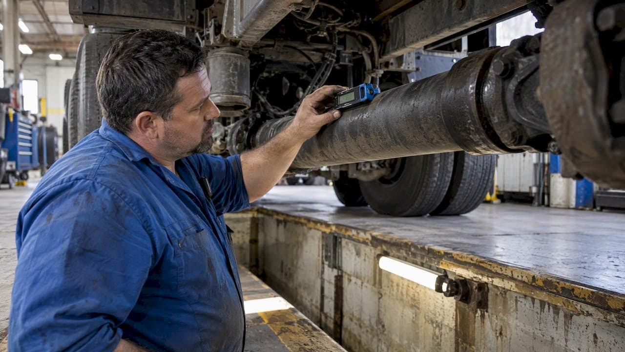
A good driveline angle setup comes down to three numbers. Measure the slope of the transmission, the driveshaft and the drive axle at ride height. Subtract to get the operating angle at each U-joint. Then make sure the angles at the two ends of each shaft are small, roughly equal, and not zero. Spicer's published rules put that at equal within one degree, at least half a degree, and 3 degrees or less for vibration-free running. The rest of this guide shows how to get there on a heavy truck, and what to do when the numbers will not cooperate.
It is written for mechanics, owner-operators and fleet shops who just swapped a transmission, replaced a differential, changed a suspension, or are chasing a vibration that will not go away.
TL;DR
- Operating angle is the difference between the slope of two connected components, such as the transmission and the driveshaft. It is not the slope of the shaft alone.
- Targets from Spicer: angles at both ends of a shaft equal within 1°, each at least 0.5°, and ideally 3° or less.
- Measure at ride height, on level ground, with a digital inclinometer, starting at the transmission and working back to the axle.
- After any transmission, differential or suspension swap, recheck the angles before you blame the part.
- Axle ratio changes driveshaft RPM, and RPM limits how much angle you can tolerate.
Table of Contents
- What driveline angle actually means
- Tools you need
- Step by step: measuring and calculating angles
- The numbers to aim for
- Fixing angles that are out of spec
- When vibration is not an angle problem
- Axle ratio and angle: how they connect
- Our perspective
- Getting the right replacement unit
- A quick pre-delivery checklist
- FAQ
- Sources
What driveline angle actually means
A U-joint does not turn at a constant speed when it runs at an angle. Its output speeds up and slows down twice per revolution. The bigger the angle, the bigger that fluctuation. Spicer's installation guidance says plainly that every U-joint operating at an angle creates a vibration, and the trick is to make the two joints on one shaft cancel each other out.
That cancellation only works when:
- The two joint angles are nearly equal.
- The yokes at each end of the shaft are in phase (the ears line up).
- The angles are small enough that what is left over stays below the vibration threshold.
People say "pinion angle" for this, and in drag racing circles it often means the angle of the pinion relative to the ground. In a truck shop, what matters is the operating angle at each joint: the angle between the transmission output and the shaft, and between the shaft and the pinion yoke. The Spicer Anglemaster guide describes it as the relationship between two slopes, such as the transmission slope and the tube slope.
A two-piece shaft with a center bearing adds a third joint and a second shaft slope. The method is the same, you just do more subtraction.
Tools you need
- Digital inclinometer or angle finder that reads to a quarter degree. Spicer recommends rounding to the nearest quarter degree, and a cheap bubble level will not get you there.
- Level floor or drive-on lift so the truck sits at normal ride height with the suspension loaded. Axle-hanging lifts change the angle you are trying to measure.
- Wheel chocks, jack stands if needed, and a flat clean spot on each component such as a yoke bearing cap, the machined face of the transmission output, or the flat on the pinion yoke.
- Notepad. Write down each reading with its sign (nose up or nose down).
Step by step: measuring and calculating angles
1. Set up the truck
Park on level concrete with the truck at normal ride height and, ideally, normal load. An empty tractor and a loaded one sit differently, and a shop that sets angles only unloaded may see vibration only under load. Chock the wheels and put the transmission in neutral so you can rotate the shaft by hand.
2. Measure the transmission slope
Place the inclinometer on a flat machined surface that is parallel to the output shaft. Zero it on the floor first. Record the reading and whether the rear of the transmission tilts up or down. The Spicer guide says to begin with the transmission and work toward the axle.
3. Measure the driveshaft slope
Rotate the shaft so you can sit the inclinometer on the tube or on a bearing cap face. Take readings at two or three positions 90° apart and make sure they agree. If they do not, the tube may be bent or the cap face dirty. Do the same for the second shaft if you have an interaxle or center-bearing setup.
4. Measure the axle slope
Put the inclinometer on the flat of the pinion yoke or a bearing cap that bolts to it. This is the pinion angle. On tandems, measure the forward-rear axle and then the rear-rear axle if an interaxle shaft is involved.
5. Subtract to get operating angles
Operating angle at each joint is the difference between the two slopes it connects. A simple example with made-up numbers for illustration:
| Component | Slope reading |
|---|---|
| Transmission | 3.0° down toward the rear |
| Driveshaft | 1.0° down toward the rear |
| Pinion yoke | 2.0° up toward the front |
Front joint: 3.0° minus 1.0° gives 2.0°. Rear joint: 1.0° plus 2.0° gives 3.0°, because the slopes point in opposite directions and so they add. The two ends differ by 1.0°, which is right at the limit. A small shim at the axle would tighten it.
Sign handling is where most mistakes happen. If you are unsure, sketch the side view of the driveline with arrows for each slope. Spicer also offers a free driveline operating angle calculator that does the arithmetic from your measurements.
The numbers to aim for
From Spicer's published rules:
- Each end of a shaft should have an operating angle of at least half a degree, so the needle bearings keep moving and do not brinell in one spot.
- The two ends should be equal within one degree (half a degree on shafts ahead of a transfer case or auxiliary device).
- For vibration-free performance, keep angles at 3° or under. Above that, stay within the maximum angle for your driveshaft RPM, shown in a chart on the same Spicer page.
The RPM chart is the part many people skip. A steeper angle that is fine at low shaft speed becomes a problem at highway speed. Compute your driveshaft RPM as engine RPM times the transmission ratio in the gear you spend the most time in, which in a direct or overdrive highway gear is close to engine speed times that ratio. Spicer's installation guide works through an overdrive example this way.
Students have even built test rigs to study this. An engineering capstone team at UC Irvine built a bench with an adjustable differential mount to see how driveshaft angle affects power transmission, vibration and rotational speed. It is a small off-road vehicle project, not a Class 8 study, but the principle is the same: more angle, more trouble.

Fixing angles that are out of spec
Axle angle too steep or too flat
On leaf-spring tractors, tapered shims between the spring seat and the axle rotate the housing and change pinion angle. On air-ride, the adjustment is usually through the torque rod length or its mounting, so check the manufacturer's service information for your suspension before you change anything.
Transmission angle off after a swap
A replacement transmission with a different tail housing, or a worn or mismatched mount, can tilt the output. Check engine and transmission mounts first, then crossmember position. Confirm the replacement unit matches the original before it goes in: our parts compatibility checklist covers what to verify.
Shaft length and center bearing
If you cannot get angles inside the limits by shimming, you may have a geometry problem, such as a center bearing bracket that has sagged or a shaft that is the wrong length. Our guide to drive shafts in heavy trucks explains how the pieces fit together.
Check the phasing and the joints
Before shimming a good geometry, confirm the yokes are in phase and the U-joints are not worn. A loose or dry joint can mimic an angle problem. Replace joints in sets if you find notchy movement.
When vibration is not an angle problem
Angles get blamed first, but run through this list before you chase shims:
- Bent or out-of-balance driveshaft, or missing balance weights.
- Worn slip yoke splines or a seized slip joint.
- Worn center bearing or cracked rubber cushion.
- Tire and wheel imbalance, or a flat-spotted tire.
- A damaged differential pinion bearing or yoke runout.
A vibration that appears only at a certain road speed often points to driveshaft RPM. One that appears under load but not coasting suggests angle change under torque, for example from a worn spring pack or torque rod bushings letting the axle wrap.
Axle ratio and angle: how they connect
Readers often ask about the best axle ratio for a semi. There is no single answer, because it depends on engine, transmission, tire size, load and route. What matters for this topic is that a lower numeric ratio, such as a 2.61, makes the pinion turn fewer times per wheel revolution, so at the same road speed the driveshaft runs slower than it would with a higher numeric ratio like a 3.08. A slower shaft tolerates a bit more operating angle. A faster one does not.

That is also why swapping ratios changes more than fuel economy. If you move to a different ratio, recheck shaft speed against the angle chart. For the engine and drivetrain side of that choice, read our piece on semi truck gear ratios and downspeeding.
Our perspective
Most of the angle complaints we hear about come after a drivetrain change, not on a truck running its original setup. A shop swaps a transmission or a differential, the part itself is fine, and the truck shakes at 60 mph. The part gets blamed and sent back, when the real problem was a mount, a shim or an angle that nobody measured.
Our advice is simple. Measure before you remove anything and write the numbers down. That gives you a baseline for the truck that actually worked. After the swap, measure again and compare. If the new angles match the old ones, the problem is somewhere else. If they do not, you know exactly where to look.
We test and inspect each part we sell, and every part carries our standard warranty, but good parts still need good installation geometry. Matching the replacement to the original ratio, yoke style and mounting before you buy saves the most time. That is why we keep a compatibility checklist on our blog and why our team is glad to help you confirm a match before you order.
— John
Getting the right replacement unit
If your measurements show a worn differential or transmission, or you are replacing one anyway, start with the exact specs from the unit you are removing: make, model, ratio and yoke or flange type. Then browse our tested and warrantied differentials and transmissions. Our inventory changes daily, and we ship the same day so the truck is not parked longer than it has to be. If you are replacing the whole power package, our truck engines page lists what is available now.
For a sense of what we stock, we list Detroit Alliance RT40-4N differential assemblies in 2.61 and 3.08 ratios.

A quick pre-delivery checklist
When the replacement part arrives, run through this before you bolt it in:
- Compare the ratio tag and yoke style against your notes. Our guide on confirming engine compatibility uses the same logic for engines.
- Check mounts and bushings, and replace any that are cracked or soft.
- Install at the original position, then measure all slopes at ride height.
- Compute the operating angles and compare to the rules above.
- Road test at the speed where any vibration used to appear, and recheck U-joint caps and fasteners afterward.
If a part fails a test after installation, our testing standards article explains what we check before parts leave the yard. It also helps to avoid the common repair parts mistakes that send trucks back to the bay.
FAQ
What is a good driveline angle for a semi truck?
Aim for operating angles of 3° or less at each U-joint, with the two ends of each shaft equal within 1°. Each should also be at least half a degree, per Spicer's published rules. If you exceed 3°, check the maximum angle for your driveshaft RPM.
Do I measure driveline angles loaded or empty?
Measure at normal ride height on level ground. If vibration only shows up under load, repeat the measurement with the truck loaded, because suspension height and axle wrap change the angles.
Can a new transmission or differential change my driveline angles?
Yes, if the replacement has a different tail housing, mounting position or yoke, or if worn mounts let it sit differently. Measure before removal and after installation so you can compare. Matching make, model and ratio to the original reduces surprises.
What is the best axle ratio for a semi?
It depends on your engine, transmission, tire size, load and route, so no single ratio wins. Lower numeric ratios lower driveshaft RPM at a given road speed, while higher ones raise it. Our gear ratio guide goes into the tradeoffs.
Sources
- Spicer Driveline Operating Angle Calculator
- Spicer Anglemaster: Measuring Angles
- Spicer Performance Driveline and Axles Installation Guide
- Anteater Baja Racing Driveline Angle Test Bench, UC Irvine